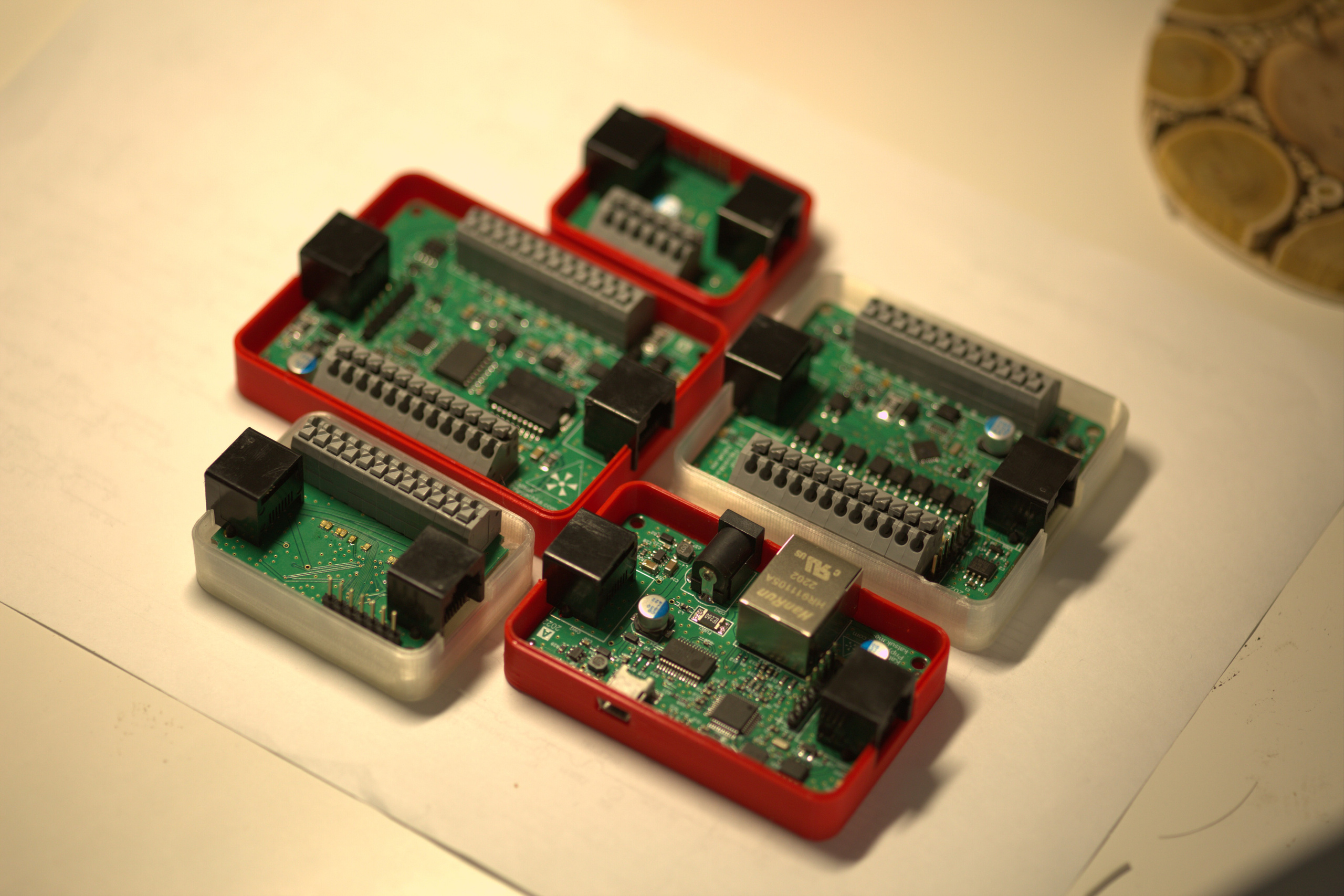
Neoden YY1
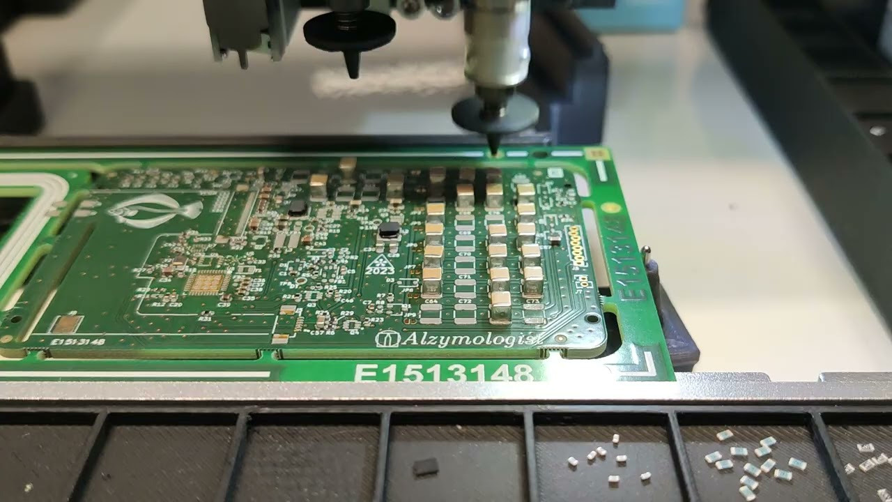
What makes it remarkable is primarily, as I mentioned, the price. It has two nozzles and a very precise mechanism that incorporates the experience gained from designing 3D printers. All the guide rails are linear, with two independent motors on the “Y” axis and two limit sensors on each side—one for coarse positioning and the other for precise positioning. The head moves along the “X” axis with its own motor, located on the head itself. The drivers are most likely TMC22-something. Both cameras are sufficiently fast, capable of detecting displacement in just 65 milliseconds, which is practically instantaneous. However, during the purchase discussions, three cameras were mentioned, but in reality, only two were installed—presumably excluding the additional one for larger components.
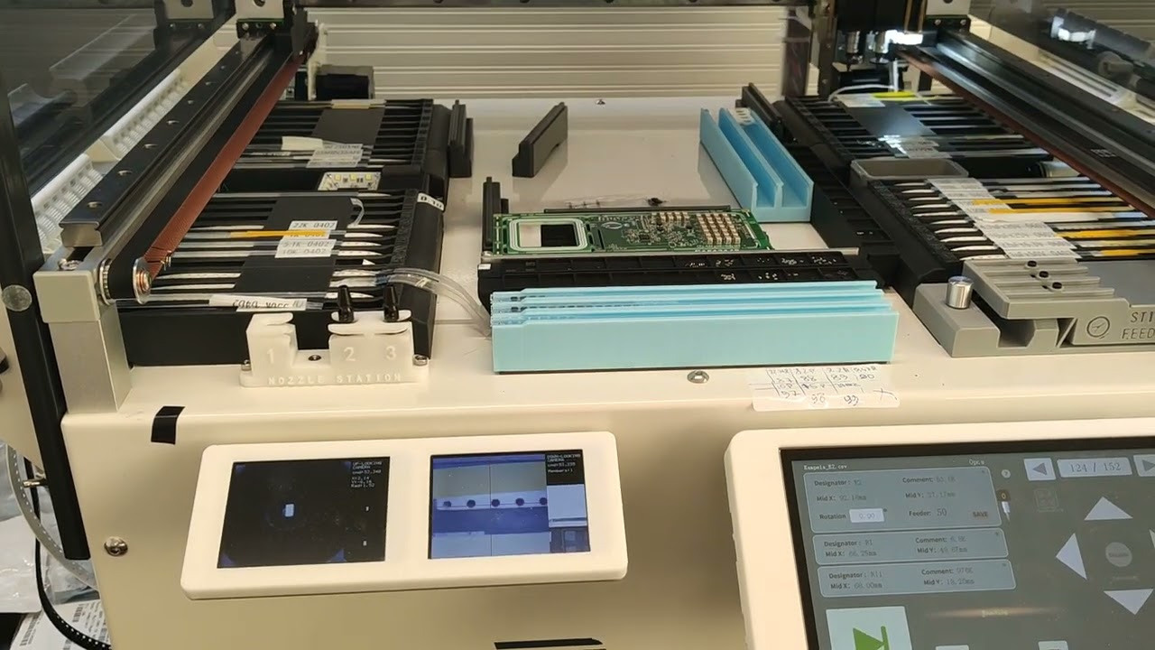
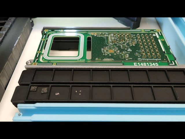
The feeders, along with many other structural elements, are 3D printed. I won’t go into the details of the quantities; what’s more interesting are the features. It offers three types of feeders: a regular reel, an insertable tape bulk tray and trays, including three vibration sensors. But the most unique thing is the trays for loose components — the bulk tray ! I came up with this idea just two months ago, and the Chinese have already been doing it for almost a year! The head with the camera approaches the tray, examines it, recognizes the contours of the components, aims, takes the first one it encounters, aligns it using the camera, and places it on the board with the same precision as the other feeders, which is at the level of 0201 components. And it also has an automatic nozzle change mechanism!
The installation speed shown in the video is 60% of 70% of the maximum. In other words, the global settings indicate 70%, but I set the components speed rate to 60%.
Now let’s talk about the nuances:
- The machine cannot be connected to a PC; it only works with an SD card.
- The manufacturer’s official response regarding firmware updates is: “You disassemble the machine, remove the board, discard it, buy a new one from us with the updated firmware, install it, and profit!” There are many bugs. The head may suddenly move beyond the sensors with the characteristic sound of stepper motors: “grrrrr”.
- Board alignment is done only using one reference mark. Typically, two reference marks are used to determine the rotation of the board. Adding a second reference mark would only require about ten lines of code. The manufacturer’s official response shines with honesty: “If we implement alignment using two reference marks, sales of our more expensive machines will decline.” By the way, if the bottom edge of the board is straight, there won’t be any issues even with 0201 components.
- Nozzle changing is programmed at the level of mechanical CNC systems from 1903. There are only four memory slots, and each slot specifies the element position, which head to use, which slot to deposit the current nozzle into, and from which slot to retrieve the new nozzle. The responsibility for logistics lies entirely with the programmer. Attempting to deposit a nozzle into an occupied slot will result in the “grrrrr” sound.
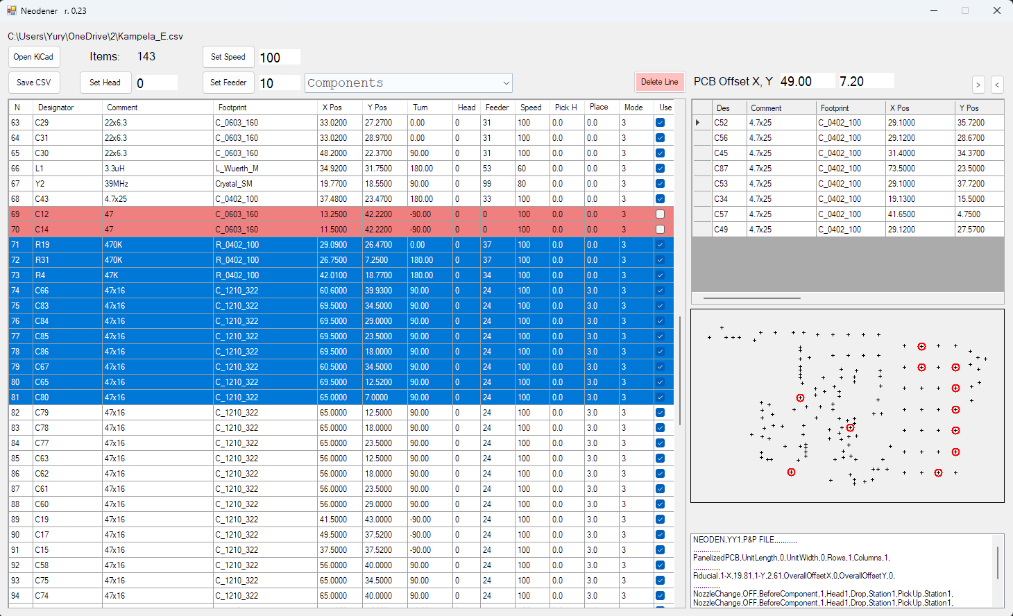
- The machine understands CSV files, but they have to be in its own format.
Well, I dusted off my C# skills (or lack thereof) and managed to whip up a nifty little program — a translator, if you will. It takes in input files in KiCad, Altium Designer, or CSV format, and churns out a CSV file on the other end. This handy tool allows you to tinker with and organize your components, provides a nifty visual representation of the elements on the board, and even lets you play around with adjusting their positions and more. It’s basically like having one of those high-end, top-dollar machines worth a small fortune.
As you might have guessed, this post is all about an exceptional program that I’ve developed
Блог
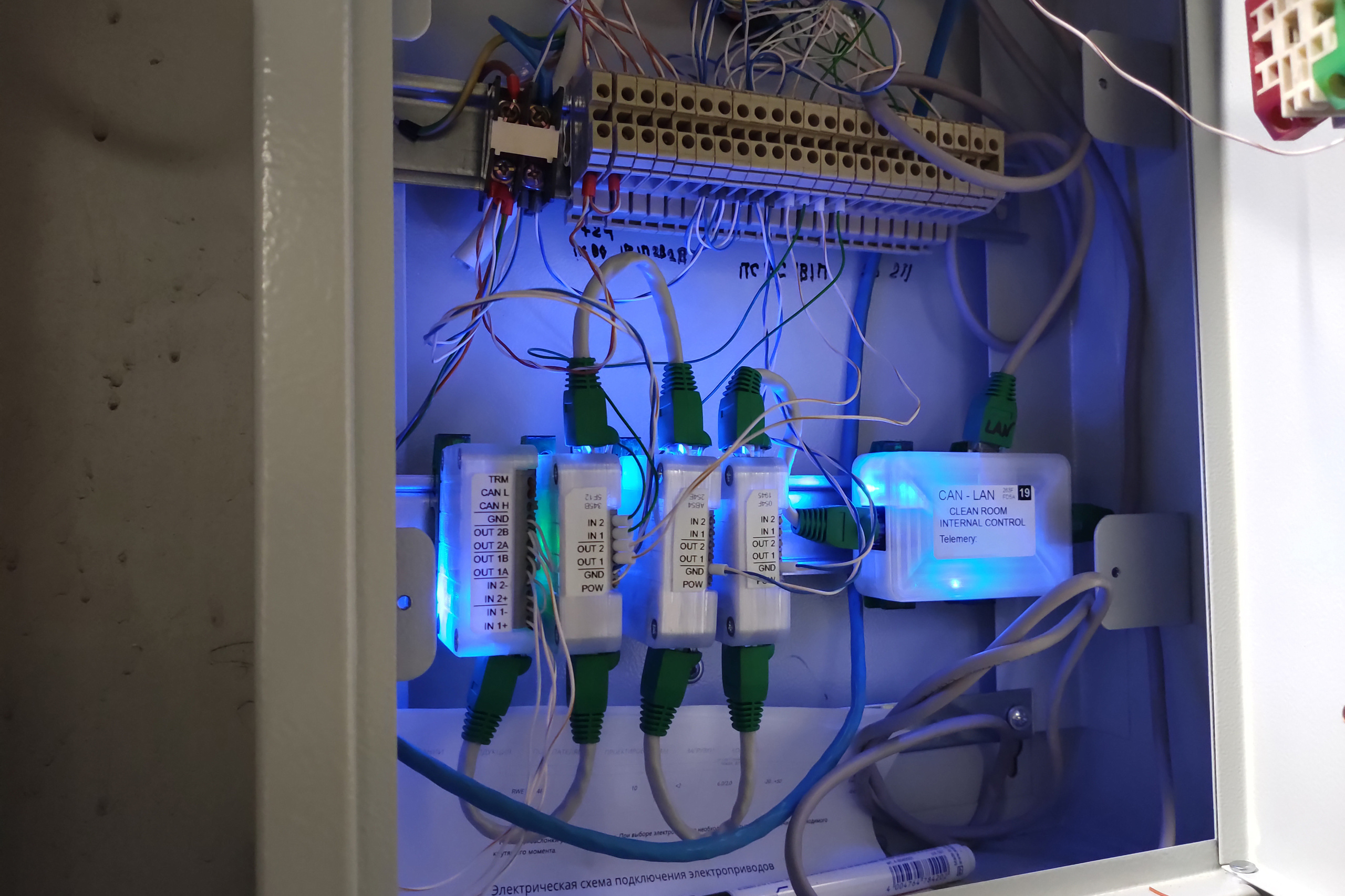
Распределенный ПЛК: управление «чистой комнатой»
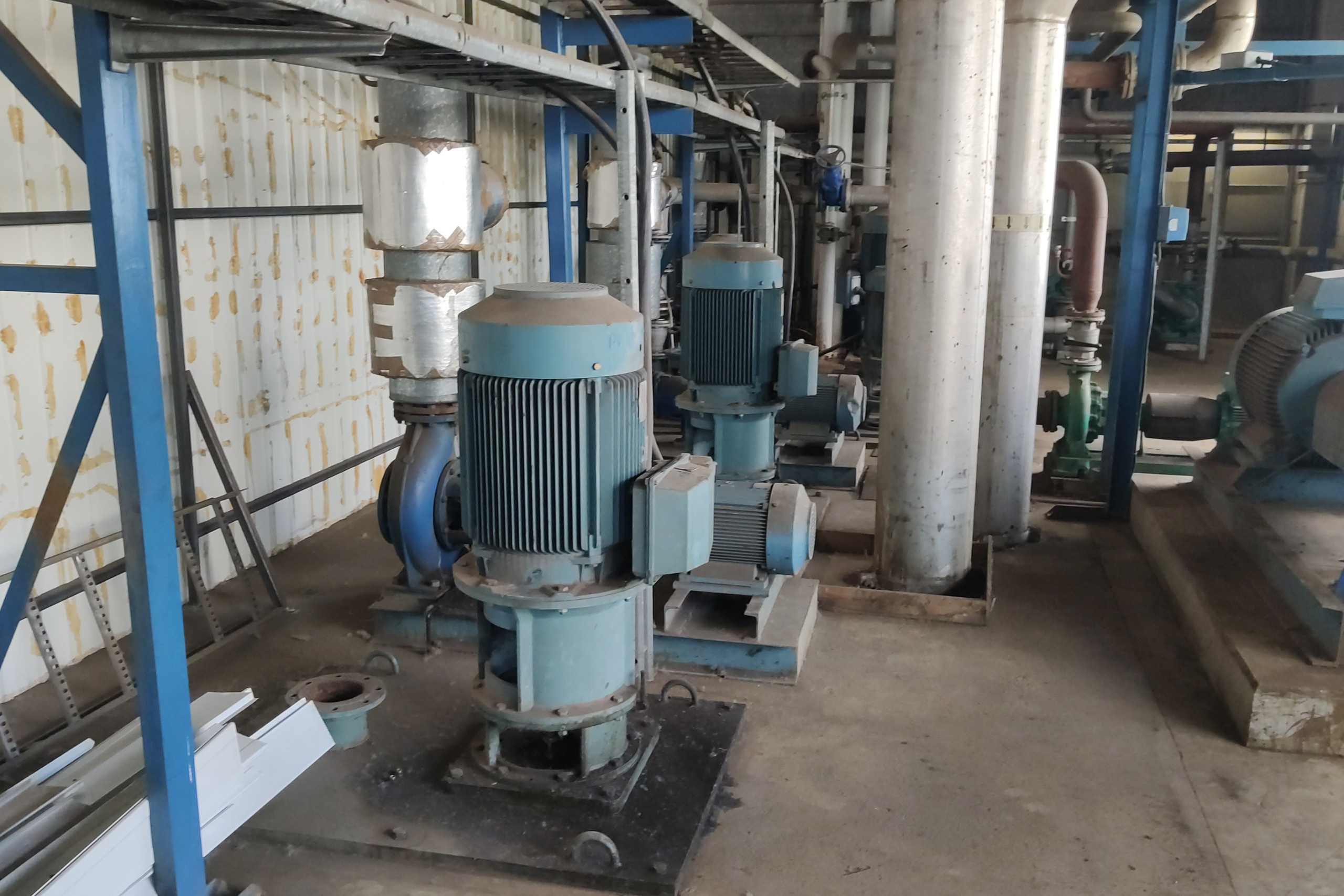
Распределенный ПЛК: управление градирней